Power Plastics
Pre-filtration and Filtration of Drinking and Industrial Water
|
Automatic Hydraulic Self-Cleaning Screen Filters |
 SERIES AF-200
Standard Features:
- Minimum operating pressure: 2.5 bar
- Maximum operating pressure: 10 bar
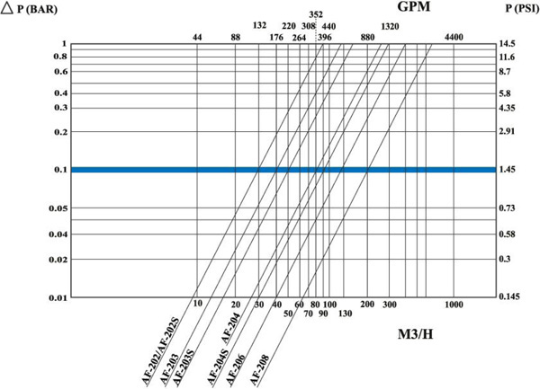
- Clean filter pressure loss: 0.1 bar
- Maximum water temperature: 65°C
- Filtration range: 50 - 3000 micron
- Control voltage: 9V DC, 12V DC, 24V AC
- Flush water consumption [at minimum working pressure]: 15 liter
- Filter housing materials: carbon steel coated with baked on epoxy
|
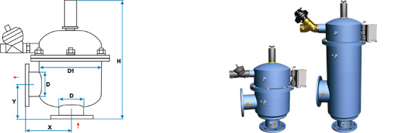
Model |
Conn. Size ØD [inch] |
Screen Area [cm²] |
* Maximum Flow Rate [m³/h] |
** Flushing Flow Rate [m³/h] |
ØD1
[inch] |
X
[mm] |
Y
[mm] |
H
[mm] |
Weight
[kg] |
|
AF-202F |
2 |
1100 |
30 |
6 |
10 |
220 |
197 |
542 |
41 |
|
AF-202FS |
2 |
1630 |
30 |
6 |
10 |
220 |
197 |
665 |
46 |
|
AF-203F |
3 |
1100 |
40 |
6 |
10 |
220 |
197 |
525 |
44 |
|
AF-203FS |
3 |
1630 |
50 |
6 |
10 |
220 |
210 |
660 |
48 |
|
AF-204F |
4 |
1630 |
80 |
6 |
10 |
220 |
210 |
660 |
47 |
|
AF-204FS |
4 |
2770 |
90 |
6 |
10 |
220 |
315 |
940 |
70 |
|
AF-206F |
6 |
4120 |
130 |
8 |
10 |
220 |
400 |
1170 |
90 |
|
AF-208F |
8 |
5240 |
200 |
8 |
16 |
305 |
450 |
1250 |
160 |
|
|
|
|
|
|
|
|
|
|
|
|
S |
Filter with large filtration area |
||||||||
|
* |
Flow rate data is for high quality water at filtration grade of 120 micron |
||||||||
|
** |
Flushing flow rate data is for minimum operational pressure [2.5 bar] |
||||||||
Pressure Loss at 120 Micron
Operation Information for AF-200 Series Hydraulic Self-Cleaning Filter [ wmv 1.6 MB ]
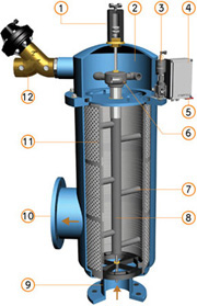
Filtration
Water enters the filter through the “Inlet” [9]. The water then reaches the fine screen [11], which purifies the flow by separating smaller particles from the water. As more water flows through, impurities build up on the fine screen.
As impurities on the screen accumulate, a pressure imbalance is built up between the internal section of the fine screen [11] and its external section.
Cleaning Process
When the difference in pressure [ΔP] reaches the preset value on the electronic control unit [4], a series of events is triggered while water continues to flow to the system units. The flushing valve [12] opens, pressure is released from the hydraulic piston [1], and water flows outside. Pressure in the hydraulic motor chamber [2] and the dirt collector [8] is significantly lowered, and the dirt collector nozzles [7] begin a suction process. The water flows through the hydraulic motor [6], which rotates the dirt collector [8] around its axis. The pressure released from the piston and the high pressure inside the filter, cause linear movement of the dirt collector. The combination of the linear movement and rotation significantly cleans the whole internal screen surface. The flushing cycle takes 5 seconds. The flushing valve [12] closes at the end of the cycle and the increased water pressure returns the system to its initial position. The filter is now ready for the next cycle, with clean and filtered water flowing through the “Outlet” [10].
General Description of the Electronic Control System
The electrical system controls the cleaning process through the differential pressure indicator [5] that closes a circuit and triggers the electronic control unit [4] that controls the opening and the closing of the flushing valve [12] via the solenoid valve [3]. The flushing cycle, which takes a total of 5 seconds, resumes its operation whenever the difference in pressure reaches the preset pressure value set on the differential pressure indicator. If the difference in pressure remains unchanged after one cycle, another cycle will start after a delay of 25 seconds.
|
|
Legend:
|
|
Installation possibilities |
||
|
Filter installation on a pipe |
Installation of more filters on a parallel pipeline |
|
|
|
||
|
|
|
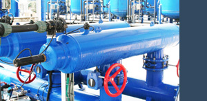 SERIES AF-800
Standard Features:
- Minimum operating pressure: 2.5 bar
- Maximum operating pressure: 10 bar
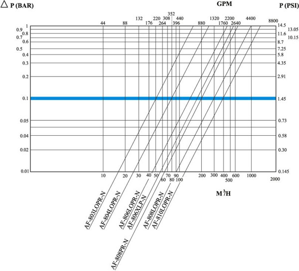
- Clean filter pressure loss: 0.1 bar
- Maximum water temperature: 65°C
- Filtration range: 10 - 3000 micron
- Control voltage: 9V DC, 12V DC, 24V AC
- Flush water consumption [at minimum working pressure]: 80 liter
- Filter housing materials: carbon steel coated with baked on epoxy
|
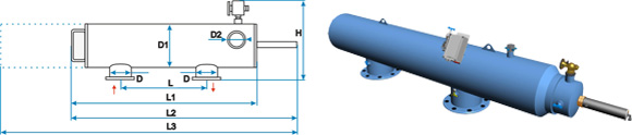
Model |
Conn.Size ØD [inch] |
Screen Area [cm²] |
*Maximum Flow Rate [m³/h] |
**Flushing Flow Rate [m³/h] |
ØD1
[inch] |
ØD2
[inch] |
L
[mm] |
L1
[mm] |
L2
[mm] |
L3
[mm] |
H
[mm] |
Weight
[kg] |
|
AF-803LOPR |
3 |
3220 |
50 |
25 |
10 |
4 |
450 |
1160 |
1389 |
2015 |
545 |
85 |
|
AF-804LOPR |
4 |
5780 |
80 |
25 |
10 |
4 |
900 |
1550 |
1800 |
2770 |
545 |
110 |
|
AF-806LOPR |
6 |
5780 |
150 |
25 |
12 |
4 |
900 |
1620 |
1855 |
2900 |
580 |
135 |
|
AF-806XLP |
6 |
8410 |
160 |
25 |
10 |
4 |
900 |
2020 |
2250 |
3700 |
555 |
175 |
|
AF-808PR |
8 |
5780 |
160 |
25 |
12 |
4 |
900 |
1810 |
2045 |
3070 |
580 |
160 |
|
AF-808LOPR |
8 |
8410 |
300 |
25 |
12 |
4 |
900 |
2210 |
2443 |
3865 |
580 |
183 |
|
AF-810PR |
10 |
8000 |
350 |
50 |
16 |
4 |
1100 |
1980 |
2480 |
3265 |
720 |
280 |
|
AF-810LOPR |
10 |
8410 |
400 |
25 |
14 |
4 |
900 |
2210 |
2445 |
3860 |
595 |
225 |
|
AF-810XLP |
10 |
11710 |
450 |
75 |
16 |
4 |
1100 |
2700 |
3145 |
5365 |
720 |
340 |
|
AF-812PR |
12 |
11710 |
600 |
75 |
16 |
4 |
1100 |
2710 |
3155 |
5365 |
720 |
350 |
|
AF-814PR |
14 |
12990 |
900 |
75 |
18 |
4 |
1270 |
2710 |
3155 |
5365 |
770 |
420 |
|
AF-816PR |
16 |
12990 |
1100 |
75 |
18 |
4 |
1270 |
2710 |
3155 |
5365 |
770 |
470 |
|
AF-816XLP |
16 |
17020 |
1500 |
75 |
24 |
4 |
1270 |
2710 |
3155 |
5365 |
920 |
700 |
|
|
|
|
|
|
|
|
|
|
|
|
|
|
|
XLP |
Extra long filter with extra large filtration area |
|||||||||||
|
LO |
Long filter with large filtration area |
|||||||||||
|
PR |
Parallel connection standard |
|||||||||||
|
* |
Flow rate data is for high quality water at filtration grade of 120 micron |
|||||||||||
|
** |
Flushing flow rate data is for minimum operational pressure [2.5 bar] |
|||||||||||
Pressure Loss at 120 Micron
Operation Information for AF-800 Series Hydraulic Self-Cleaning Filter[ wmv 2.2 MB ]
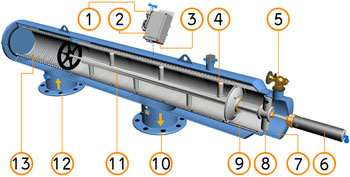
Filtration
Water enters the filter through the “Inlet” [12] and passes through the coarse screen [13] that functions as a “first stop” for rough particles. Water then reaches the fine screen [9], which further purifies the flow by separating smaller particles from the water. As more water flows through, impurities build up on the fine screen. As impurities on the screen accumulate, a pressure imbalance is built up between the internal section of the fine screen [3] and its external section.
Cleaning Process
When the difference in pressure [ΔP] reaches the preset value in the electronic control unit [2], a series of events is triggered while the water continues to flow to the user. The flushing valve [5] opens, pressure is released from the hydraulic piston [6] and water flows outside. Pressure in the hydraulic motor chamber [7] and the dirt collector [11] is significantly lowered, and the dirt collector nozzles [4] begin a suction process. The water flows through the hydraulic motor [8] which rotates the dirt collector [8] around its axis. The pressure released from the piston [6] and the high pressure inside the filter cause linear movement of the dirt collector. The combination of the linear movement and rotation significantly cleans the entire internal screen [9] surface.
The flushing cycle takes about 10 seconds. The flushing valve [5] closes at the end of the cycle and the increased water pressure returns the hydraulic piston [6] to its initial position. The filter is now ready for the next flushing cycle, with clean and filtered water flowing through the “Outlet” [10].
Note: At the back of the piston is an indicator that pops up when the piston reaches the end of its motion. This indicator helps us to check whether the dirt collector, inside the filter, completed it’s motion.
General Description of the Electronic Control System
The electronic system [2] initiates the cleaning process based on either time differential [DT] and / or pressure indicator differential. The trigger closes a circuit and then triggers the electronic control unit after a delay of 15 seconds. The electronic control unit [2] controls the opening and the closing of the flushing valves [5] via the solenoid valve [1]. The flushing cycle, which takes a total of about 10 seconds (can be adjusted by the operator), resumes its operation whenever the time cycle ends or the difference in pressure reaches the preset pressure value set in the controller. If the difference in pressure remains unchanged after one cycle, another cycle will start after a delay of 15 seconds.
|
|
Legend:
|
|
Installation possibilities |
||
|
Filter installation on a pipe |
Installation of more filters on a parallel pipeline |
|
|
|
||
|
|
|
|
Special Options and Features: |
- High pressure range: 16, 25, 40[bar]
- High temperature range: withstands temperature up to 95°C
- Anti frost: special control system for cold climate conditions
- Electric current: 110V AC, 230V AC, single phase, 3-phase, 24V DC and solar energy
- Construction materials: stainless steel 304L or 316L, and titanium
- Available controllers: electronic, timer, air-actuated, computerized and custom designed
Although the filters are manufactured in a top technical and technological quality, their installation, operation and maintenance are very easy. They are intended for a continuous operation and are non-demanding in terms of both rinsing water consumption and consumption of energy.
If you require removal of any mechanical impurities from water, please contact us and we will draw up, free of charge, a proposal for the most suitable solution for you, on the basis of a raw water analysis, required filtration capacity [m³/hr] and required quality of output water.
|
High Quality Water No Matter Where It Comes From |

FILTRATION & WATER TREATMENT

EXCELLENCE IN
DESIGN & MANUFACTURING
tel./fax: +420 566 630 843
gsm: +420 775 630 843


Welcome to the website of Power Plastics s.r.o.